Lift/Propulsion engines
7. The lift/propulsion engine is capable of providing thrust for both normal wing borne flight and for lift. This is achieved by changing the direction of the thrust either by a deflector system consisting of one, two or four swivelling nozzles or by a device known as a switch-in deflector which redirects the exhaust gases from a rearward facing propulsion nozzle to one or two downward facing lift nozzles (fig, 18-4).
 |
| Fig. 18-4 Thrust deflector systems. |
8. Thrust deflection on a single nozzle is accom- plished by connecting together sections of the jet pipe, the joint faces of which are so angled that, when the sections are counter-rotated, the nozzle moves from the horizontal to the vertical position (fig. 18-5). To avoid either a side component o! thrust or a thrust line offset from the engine axis during the movement of the nozzle it is necessary that the first joint face is perpendicular to the axis of the jet pipe. If it is desired that the nozzle does not rotate, as may be the case if it is a variable area nozzle, a third joint face which is perpendicular to the axis of the nozzleis required.
 |
| Fig. 18-5 Deflector nozzle. |
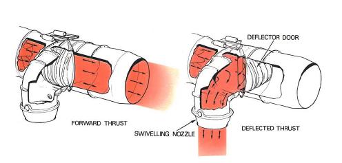
9. The two and four nozzle deflector systems use side mounted nozzles (fig. 18-6) which can rotate on simple bearings through an angle of well over 90 degrees so that reverse thrust can be provided if required. A simple drive system, for example, asprocket and chain, can be used and by mechanical connections all the nozzles can be made to deflect simultaneously. For forward flight, to avoid a high performance loss and consequent increase in fuel consumption, careful design of the exhaust unit and nozzle aerodynamic passages are essential to minimize the pressure losses due to turning the exhaust flow through two close coupled bends (fig. 18-7).
 |
| Fig. 18-6 Side mounted swivelling nozzle. |
10. The switch-in deflector consists of one or a pair of heavily reinforced doors which form part of the jet pipe wall when the engine is operating in the forward thrust condition. To select lift thrust, the doors are moved to blank off the conventional propelling nozzle and direct the exhaust flow into a lift nozzle (fig. 18- 8). The lift nozzles may be designed so that they can be mechanically rotated to vary the angle of the thrust and permit intermediate lift/thrust positions to be selected.
 |
| Fig. 18-7 Nozzle duct configuration. |
11. A second type of switch-in deflector system is used on the tandem fan or hybrid fan vectored thrust engine (fig. 18-9). In this case the deflector system is situated between the stages of the fan of a mixed flow turbo-fan engine. In normal flight the valve is positioned so that the engine operates in the same manner as a mixed flow turbo-fan and for lift thrust the valve is switched so that the exhaust flow from the front part of the fan exhausts through downward facing lift nozzles and a secondary inlet is opened to provide the
 |
| Fig. 18-8 Switch-In deflector system. |
required airflow to the rear part of the fan and the main engine. On a purely subsonic V/STOL aircraft where fuel consumption is important the valve may be dispensed with and the engine operated permanently in the latter high by-pass mode described above.
 |
| Fig. 18-9 Vectored thrust engine. |
12. Thrust deflecting nozzles will create an upstream pressure distortion which may excite vibration of the fan or low pressure turbine blades if the nozzle system is close to these components. Snubbers (Part 3) may be used on the fan blades to resist vibration. On the low pressure turbine, shrouds at the blade tips (Part 5) or wire lacing may be used to achieve the same result.
No comments:
Post a Comment