Wednesday, August 14, 2013

Supercharger Development in the U.S. During the Inter-War Period Part 3 - Developments in the U.S.

Developments in the U.S.
Fig. 3.  Miller supercharger designed by Dr. Moss. An unusual feature is the small impeller installed in the intake nozzle. (Courtesy Miller/Offenhauser Society)
Dr. Sanford A. Moss (1872 – 1946) made the turbocharger practical, advanced the cause of gas turbines, and ended his long career by pressurizing civilian airliners. Earning a doctorate from Cornell in 1903, he was immediately hired by General Electric to head up their turbine research facility at West Lynn, Massachusetts, where he would remain until retirement in 1938. Some idea of his thinking comes about from his habit of asking prospective employees if, as a child, they had ever taken a clock apart to see how it works. For “A young fellow who never took a clock apart can never become a mechanical engineer.”

Tuesday, August 13, 2013

Supercharger Development in the U.S. During the Inter-War Period Part 2 - Types

Types
After the First World War supercharger development concentrated on gear-driven centrifugal compressors and turbochargers. NACA was almost alone in the pursuit of the Roots blower.

Fig. 1. British supercharger drive, circa 1920. Engine oil provided lubrication on this example.  German designs often used a separate reservoir and dedicated oil pump.
Fig. 2.  Centrifugal clutch patented by Heron and Green.
Gear-Driven Centrifugal Blowers
A centrifugal compressor consists of an impeller and a diffuser housed in a helical casing, or scroll. The diffuser, sometimes called the stator, occupies the annular space between the impeller and scroll. Passages created by the diffuser vanes open wider as they approach the discharge throat. Vanes on the impeller wheel are arranged radially and may be straight or curved. The use of curved vanes came relatively late in the period and improved efficiency.
Air enters at the impeller hub, rotates with the impeller and, under the influence of centrifugal force, moves outward in a path defined by the impeller vanes. Upon contact with the diffuser, the air expands and slows, converting much of its kinetic energy into static pressure.
Because the impeller cannot be allowed to make physical contact with the shroud, there is always some leakage between the vane tips and the scroll. The seal consists of air, an elastic medium. At low rotational speeds the impeller merely flays about delivering little or no output. As tip velocity increases, the air seal becomes more positive and the compressor begins to pump. Unlike Roots blowers that move the same volume of air per revolution, centrifugal compressors are dynamic machines, whose output increases as the square of speed—double the speed and the output theoretically quadruples.

Inertia
Work on aircraft superchargers began in Europe around 1915 with the intent of normalizing output at high altitudes. Initially experiments were carried out with a variety of pumps, but within a year or so the French settled on the Rateau turbocharger. The Royal Aircraft Factory

Monday, August 12, 2013

Supercharger Development in the U.S. During the Inter-War Period Part 1

This paper describes some major developments in aircraft superchargers that took place in the United States between 1918 and the Second World War. Emphasis is on the supercharger itself. Other developments that contributed to the success of the technology—doped fuels, reduction gears, variable-pitch propellers—will have to wait for another time.

Rationale
Engines induct air by volume, but consume oxygen by weight. As the atmosphere thins at high altitudes, fewer oxygen molecules are available for combustion. A naturally-aspirated engine loses about half of its rated power at 20,000 ft. Forced induction is a merely a way to increase the density of the charge.

Normalized Boost
Initially researchers viewed superchargers solely as a means of altitude compensation. The aim was to restore lost power by maintaining, but never exceeding, sea-level manifold pressure as the airplane climbed. As Dr. Stanford Moss put it, a normalized supercharger “kidded the engine into thinking it was a sea level.”[1] Brake mean effective pressure (BMEP), exhaust temperature and the heat lost to the cooling system remained within design limits.
The ability to operate with impunity at high altitudes resulted in increased speed and slightly more than anticipated engine power. The rarified atmosphere reduced drag on the airplane and backpressure on the exhaust. The loss of lift could be compensated for by greater angles of attack.

Ground Boost

Sunday, August 11, 2013

The Rolls-Royce W2B/23 Welland

This turbo-jet was the first British production engine. The prototype F.9/40, DG202/G, powered by Rolls-Royce 1,700 lb W2B/23 engines, was flown by Michael Daunt, from Barford St. John airfield on July 24, 1943. In November this aircraft was delivered to the Rolls-Royce base at Hucknall for Welland development.
Two Rolls-Royce Welland turbo-jets were installed in the first production Meteor Mk.1, EE210/G, which was test flown by Michael Daunt on January 12, 1944. This Meteor was then sent to the United States in exchange for a General Electric J31-GE-powered Bell YP-59 Airacomet, RG362/G. The Meteor was first flown at Muroc AFB by John Grierson on April 15. Several test flights followed. By December, the Meteor had been shipped back to the U.K.
The Rolls-Royce Welland entered service with the RAF Meteor Mk.1 jet fighters EE211-229 and Meteor Mk.3/EE230-244. The first of these Meteors was delivered to No.616 Squadron RAF in May 1944, equipped with 1,600 lb thrust engines rated at180-hours between overhauls. Flying from RAF Manston, near the English channel, the Squadron first saw action against the V-1 flying-bombs en-route to London on July 27, 1944. The first of thirteen V-1s to be destroyed was on August 4, when Flying Officer Dean used his wing tip to tip a V-1 off its course and saw it crash onto open ground.

The Rover W2B

The W2B was the Rover version of the Whittle engine, ordered into production by the British Ministry of Aircraft Production in 1942. This “reverse-flow”, 43.5-inch diameter engine, featured a 19-inch, double-sided impeller, 10 “reverse-flow” combustion chambers and a single-stage turbine. Engine weight was some 850 lbs.
To improve the “surging” problem found at altitude, Maurice Wilks and his staff at Rover, Barnoldswick in Lancashire, developed 20-vane diffusers to Whittle’s design. With the thrust still at 1,000 lbs, Mr. J.P. Herriot from A.I.D. came to Rover and with improved turbine material, achieved a 25-hour test at 1,250 lbs in November, 1942.
From July 10, 1940, test pilot Jerry Sayer, was only able to make taxiing runs with 1,200 lb thrust Rover W2B/23 turbo-jets fitted to the first twin-engined Gloster F.9/40 prototype fighter, DG202/G.
The Rover W2B turbo-jet was first flown in the tail of a twin-engined Wellington test-bed, Z8570/G, from Hucknall, on August 9, 1942.

Wednesday, August 7, 2013

How to control Flying Radio Control I.C. Powered Model Aircraft ? The Receiver & The Battery part

The Receiver 

This is the small rectangular sealed box with a length of thin wire protruding from one end and a set of sockets and exposed pins at the other end. These sockets are provided to receive the plugs attached to the servos. Normally the sockets are marked with the appropriate designated function. The number of functions available will normally range from 4 up to 7 or 8 depending on the model purchased. There will also be another input socket designated for the battery lead.

There will also be a socket to take a receiver crystal. The crystal will normally be fitted in situ when a new system is purchased. Crystals are usually supplied in matched pairs designated Tx (Transmitter) & Rx (Receiver), the frequency value in MHz and/or the channel number. Never interchange the Tx and the Rx crystals.

Servos 

Tuesday, August 6, 2013

How to control Flying Radio Control I.C. Powered Model Aircraft ? The Radio Control System Part 2


Antenna
Batteries
Battery Meter
Crystal
Gimbals (Stick)
Handle
Power Switch
Trainer Switch
 The telescoping tube that transmits the signal
 The device that provides power to the transmitter
 The device used to monitor the strength of the transmitter batteries
 The device that sets the radio frequency of the transmission
 The device that allows the user to input desired control movements into the transmitter
 The device for carrying the transmitter
 The switch used to apply battery power to the internal components of the transmitter
 The switch used to allow an instructor to give control of a model to the student
Trim Lever  Slides used to adjust control surfaces during flight

Monday, August 5, 2013

How to control Flying Radio Control I.C. Powered Model Aircraft ? The Radio Control System Part 1

The Radio Control System 

There are many modern radio systems to choose from.  Each manufacturer offers a wide range of options from simple 2 - channel to computer assisted 8 - channel systems (and more!).  The choice is limited only by your financial budget. As a beginner you should discuss the choice of system with your intended instructor.  There are several good reasons for doing this, the primary reason being that the student's systems must be compatible with the instructor's system if a buddy box link is proposed.  This option will be covered in more detail later.
 
All standard radio systems consist of four (4) basic components.  Transmitter     - The unit that takes the control input from the pilot through the gimbal mounted sticks, encodes this input and sends it to the aircraft as a radio signal.
 Receiver - The unit that receives the signal from the transmitter, decodes it and  routes it to the appropriate servo.
Servos - These devices convert the decoded signals into a mechanical force that  is directed via a linkage to the appropriate control surface.
Batteries - The component that provides the electrical supply enabling the other  components to function.

Sunday, August 4, 2013

How to control Flying Radio Control I.C. Powered Model Aircraft ? The Power Plant part

The Power Plant 

The most suitable engine size for almost all trainers is a 6.5cc. (0.40cu.in. or "forty") size.  When it comes to choosing an engine for your trainer, the choice is almost mind boggling.  So many manufacturers, each one offering several engines in the same capacity range.  So which do you choose?  You can buy cheap or you can buy reliable. "Reliable" means it starts, ticks over, runs and stops when it's meant to and will probably cost an extra £10 to £15 more than a cheap offering.  If you enjoy the challenge of getting an engine to run properly when it doesn't want to - buy cheap.  If you want to learn to fly - buy reliable.

A good engine isn't necessarily a powerful one.  What you need in a suitable trainer engine is one that starts easily, is easy to set up and runs consistently.  When you're learning, most of the time you are unlikely to have the engine running at much more than half throttle.  Ask around at the club and watch anyone else learning to fly.  Notice how easy it is to get the engine started.  Does the engine run consistently throughout the flight - full throttle on take off then back to about half throttle?  Does it falter just after take-off or die in the air unexpectedly?

Saturday, August 3, 2013

How to control Flying Radio Control I.C. Powered Model Aircraft ? Ease of Repair Part

Ease of Repair 
You have to accept that your first—and maybe your second—model could well be damaged in the course of your learning how to fly.  With this in mind, you should look for a trainer that has relatively few parts that can be easily repaired if they are broken.

Wood and foam are high on the easy-to-fix list; molded plastic, fibreglass or epoxy resins are more difficult to repair.  Cyanoacrylate (CA) glue (sometimes called ‘superglue’ or ‘cyano’) and epoxy are the most common adhesives used  for gluing wood parts together.  Aliphatic resin or special white glues available from your model shop are excellent for gluing foam pieces back together.

Parts availability Often it is easier to replace damaged parts than to repair them.  Try to select a model that has replacement parts readily available via your model shop from the manufacturer. Some model kits have extra wings supplied in case you damage one beyond repair.

Friday, August 2, 2013

How to control Flying Radio Control I.C. Powered Model Aircraft ? The Instructor & Choice of Model Parts

The Instructor 
It’s not completely unknown for individuals to teach themselves to fly model aircraft but more fail miserably than actually succeed.  Without the help and support of an experienced flyer, you are almost certain to destroy your pride and joy at the first attempt.

Gravity is a very unforgiving adversary in this battle and unless you are very lucky, you will loose the initial confrontations.  Even if you have a very commendable attitude and a determination to not be defeated, the encounters will empty your financial coffers quite rapidly.  Repairs or replacement aircraft, engines and radio equipment can be a major drain on finances.
Why make life difficult for yourself when, for the price of a meal out for two, you can have a full year’s club membership and the help of a qualified tutor at your disposal?  Most clubs provide free tuition for novice members.

A proficient instructor can be the best aid to your success in this adventure.  Most club instructors have been through a process of selection and special training to provide them with the skills they need to teach others.
Talk to each of the appointed instructors to find one you can relate to.  Bear in mind also that your instructor has to have your respect.  This relationship is very much a two way exercise and requires you to be receptive and prepared to obey instructions as required.  If the club appoints an instructor that you feel uncomfortable with, don’t be afraid to explain this to the training officer and find one you are happy with.  It is very important that you and your instructor have a strong measure of both trust and understanding.

Once you are happy with your instructor, take some time to sit down and have them explain the programme you will follow (they will probably do this anyhow).  This is important so that you know exactly what will be expected of you.  Not only this, but you will have some idea of the time frames required to fulfill the various stages of the programme.

Choice of Model 

Thursday, August 1, 2013

How to control Flying Radio Control I.C. Powered Model Aircraft ? - Essential Considerations & Where To Fly Parts

Essential Considerations 
We are going to work only with fixed wing model aeroplanes powered by two stroke fuel engines.  The basic advice is also relevant to helicopters, as far as engines, radio and starting kit is concerned.  There are some basic fundamental factors you must accept and appreciate before you even start.

1) Where you are going to fly your model.
2) The necessity for you to be protected by third party indemnity insurance.

Both of these essentials can be fulfilled by approaching and joining your local model flying club.  Such organizations will, in most instances, have negotiated flying rights with a local landowner, council, etc. or even own their own flying field.

Most established clubs will be affiliated to the national governing body that controls model flying in your country.  As part of that affiliation they will have inclusive membership insurance at a fraction if the price it would cost you to insure yourself.  Not only does club membership carry these most useful benefits, there will almost certainly be a pilot training scheme for you to take advantage of.  Many clubs today even provide a suitable club trainer and control setup for you to ‘cut your teeth on’, so to speak.  If you haven’t already been put off your initial enthusiasm by the above reality check, then let’s move on to some further considerations.

a) Where are you going to learn to fly your model?
b) Who’s going to teach you?
c) What sort of model will you choose?
d) How are you going to power it?
e) What radio equipment will you choose to control it?
Let’s take each of these basic considerations in turn.

How to control Flying Radio Control I.C. Powered Model Aircraft ? Introduction Part 1


Where to Fly 

Sunday, July 28, 2013

How to control Flying Radio Control I.C. Powered Model Aircraft ? Introduction Part 1

Part 1 Introduction 

 Welcome to the world of Radio Control Model Flight.  So what got you interested in this fascinating but almost masochistic hobby!?  A hobby where, if you take the wrong approach, you will almost certainly enter and leave (in fairly rapid succession) a disillusioned and much poorer individual.

You’ve probably encountered some model fliers enjoying themselves at the club field wringing all sorts of manoeuvers out of their models.  You’ve watched in awe as these miniature flying machines defy all the rules of gravity and appear to be capable of doing things even full size aircraft can’t do.  You’re thinking to yourself “Oh to be able to do what these guys can do”.  Well strange as it may seem, YOU CAN!

Saturday, July 27, 2013

Revell's 1/32 scale Messerschmitt Bf 109 G-6 Part 2

Construction Impressions


This build was straight from the box, so I kept the moulded-on harness straps even though I was not keen on them. In the end though, I was really pleased with the way they looked after careful painting. Oddly, the shoulder straps appear to disappear behind the seat pan but it will be a simple matter to add hardware and maybe a short extension to the straps.

Revell's 1/32 scale Messerschmitt Bf 109 G-6 Part 1

This model was built straight from the box for a forthcoming book to be released by ADH Publishing.
Revell's initial release will include parts for an early and a late Bf 109 G-6, including:
  • alternative cockpit parts (different cannon breech covers, alternative footrests, and battery box option behind the pilot's head)
  • both early framed and clear-vision Erla canopies; and two windscreen versions
  • standard and tall tails
  • long and short tail wheel strut and alternate tail wheel well fairings
  • treaded and smooth main wheels
  • Morane mast with clear insulator base and DF loop for late version
  • early and late shell ejector panels under the fuselage
  • alternate starboard side engine cowls (with and without the G-5-style compressor bulge).

Sunday, July 14, 2013

Human Posture Analysis CATIA design

Human Posture Analysis


Human Posture Analysis - Mirror Copy

Human Posture Analysis - Segment Coloring

Human Posture Analysis - Adapting Range of Motion to Keep Best Posture


Human Posture Analysis - Adapting Range of Motion to Keep Best Posture

Adapting Range of Motion to Keep Best Posture

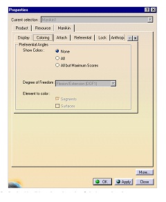
The purpose of this task is to set the angular limitations of the selected segments so that these limitations correspond to the best range of motion, that is, the range of motion where the postural score is the highest.
Please refer to Editing Preferred Angles for information on how to create preferred angles and assign scores to individual ranges of motion.
1. To optimize the range of motion of any particular set of segments, first select the desired segment(s) and then click on the Optimize Posture icon.  
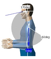
For each selected segment and for the current active degree of freedom, the command looks for all preferred angles created that have been assigned scores. The command then sets the angular limitations to the range containing the highest score.
When this command is run, the posture of the segment(s) may change in order to reflect the new angular limitations.
It is possible to use this command to optimize the posture of the manikin as a whole. To do this, select the Body node in the specification tree before activation the Optimize Posture command.  
This is particularly useful if the manikin's movements must be restricted to the "comfort zone". The postural score of such a manikin will stay at its highest, no matter how the manikin is moved. For more details, please refer to Using the Postural Score.
It is possible that some or all of the selected segments may contain no preferred angle information or some of the angles may be locked. In these cases, and these cases only, the Optimize Posture command might fail. If the command fails for a subset of the selected segments, a message window will appear displaying the list of segments for which the optimization failed. 
2. To reset the angular limitations of a manikin, select the segments that must be reset and click on the Reset to Default Angular Limitations icon. 

Human Posture Analysis - Segment Coloring

Segment Coloring
Access to segment coloring is through the Properties dialog box. 
1. Right-click the manikin in the specification tree and select Properties from the contextual menu. The  Properties dialog box appears. 
2. In the Manikin tab, select the Coloring sub-tab. 
●     Show Colors: These radio buttons are used to enable and disable the coloring. 
❍     None deactivates the coloring.
❍     All activates the coloring.
❍     All but Maximum Scores activates the coloring on all segments except those with scores at their maximum. This feature can be used, for instance, to display colors only if the manikin goes out of its comfort zone.
●     Degree of Freedom This combo is used to choose the degree of freedom to activate. This combo is enabled only if the coloring feature is active.

Human Posture Analysis - Mirror Copy


Mirror Copy
The mirror copy function will copy the preferred angles of the selected segment (in all degrees of freedom) onto the opposite side of the manikin.
Mirror copy functionality can only be applied to segments that have an equivalent segment on the other side. If there is no equivalent segment, Mirror Copy will be disabled in the contextual menu. It is also disabled in the contextual menu when you select the entire manikin or the "Body" node.
Swap
The preferred angles of each selected segment will be copied to the opposite side of the manikin and vice versa. If a segment does not have an equivalent on the opposite side, Swap will be disabled in the contextual menu.
Using and Optimizing the Postural Score
This procedure describes how to use the List and Chart displays in the Postural Score Analysis dialog box and optimize the postural score. It also describes how to set segment coloring and how to customize the list and chart display in the Postural Score Analysis dialog box.

Human Posture Analysis - Editing Preferred Angles

Editing Preferred Angles
This procedure describes how to use the Edit Preferred Angles command. By dividing the total range of motion of the manikin into a certain number of ranges, it is possible to compute a global and a local score that quantifies the current posture. The Edit Pref
erred Angles command enables the user to define these ranges on individual DOFs. Selecting another segment while the command is running opens the Preferred angles dialog box for the new segment and closes it for the previous one.
1. Select the Edit Preferred Angles icon  and then select a  segment. The preferred angles for that segment are displayed.


2. With the right mouse button, click anywhere in the white range of motion region to display the contextual data.
Click on an option to activate it.

Human Posture Analysis - Locking DOFs

Locking DOFs
1. To lock a degree of freedom, select the lock icon  and then select the segment(s) to be locked. Multiple segments can be locked at the same time
if they are pre-selected before the activation of the command.
If the operation is successful, a message window will appear displaying the segments that have been locked.
2. Follow these steps to discover the existing locked segments on a specific manikin: 
a. Access the manikin Properties panel. To do this, right-click on the manikin from the product tree and select Properties. 
OR select Edit -> Properties from the main menu.
The Properties panel appears.
b. Select the Manikin tab which is the last tab of the panel. c. Select the Lock sub-tab which is dedicated to lock/unlock 

Human Posture Analysis - Selecting Manikin Display Attributes

Selecting Manikin Display Attributes
This procedure describes how to set and edit manikin display attributes.
In the Utilities toolbar, select the Display Attributes command icon . The Display Attributes dialog box appears with the following 
choices:
Rendering


●     Segments
●     Ellipses
●     Surfaces
●     Resolution
Vision
●     Line of sight
●     Peripheral cone
●     Central cone
●     Cone type
Others

Human Posture Analysis - Angular Limitations Undo/Redo

Angular Limitations Undo/Redo
This procedure describes how to use the Undo/Redo feature with angular limitations. Undo/Redo allows you to reverse (cancel) the last angular limitation parameters applied to the manikin.

Undo
Click the Undo icon  in the Standard toolbar to execute the Undo command.
The images below show the state of a manikin after applying the Undo command to a particular set of angular parameters.

Redo
This command repeats the last cancelled action. Click the Redo icon  in the main menu toolbar to execute the Redo command.
A Redo operation can also be undone. For example, you can restore the last angular limitation parameters by invoking the Undo  command.

Human Posture Analysis - Displaying and Editing Angular Limitations

Displaying and Editing Angular Limitations
This procedure describes how to display the values of the angular limitations for the DOF (degrees of freedom) that is currently active. It also describes how to set angular limitations as a percentage.
1. Select the Edit Angular Limitations icon   and then select a segment. 
The limits arrows are displayed. These arrows are set by default at the mean values of movement limits. The colored region represents the total range of motion for that DOF. 

●     The green arrow shows the upper limit.
●     The yellow arrow shows the lower limit.
●     The blue arrow is used to change the position of the active segment.
Selecting another segment while the command is running opens the angular limitations for the new segment and closes them for the previous one.

Human Posture Analysis - Animate Viewpoint

Animate Viewpoint
This option zooms on the selected segment and changes the viewpoint in order to provide the best possible view for that degree of freedom. This improves the range of motion chart display and as well as the capability to better manipulate the blue arrow. 
Predefined Postures
Use the Predefined Postures functionality to assign a predefined posture to the worker. From the Predefined Postures list, choose from the six available postures.

Human Posture Analysis - Lumbar

Lumbar

Hand filter:
●     When the Hand Only option is selected, only the hand is available in the Segments multi-list.
●     When the Hand and Fingers option is selected, all of the fingers are also available in the Segments multi-list.
Side:
When you edit certain segments such as the arm, you can choose which side you want to work with: Left or Right.
Left is the default option when the dialog box opens. 
Degree of Freedom
From the Degree of Freedom list, you can choose from three types of DOFs: 
●     flexion/extension
●     abduction/adduction
●     medial rotation/lateral rotation
The default when the dialog box opens is flexion/extension.

Human Posture Analysis - Getting Started

Getting Started
This tutorial provides an overview of Human Posture Analysis functionalities. It provides a step-by-step scenario showing you how to use key functions.  
The task described in this section is:
Creating a Manikin

Creating a Manikin

User Tasks

Saturday, July 13, 2013

Human Posture Analysis - Accessing Sample Documents

Accessing Sample Documents
To perform the scenarios, sample documents are provided. For more information about this, refer to "Accessing Sample Documents" in the Infrastructure User's Guide.

Conventions
Certain conventions are used in CATIA, ENOVIA & DELMIA documentation to help you recognize and understand important concepts and specifications.
Graphic Conventions
The three categories of graphic conventions used are as follows:
●     Graphic conventions structuring the tasks
●     Graphic conventions indicating the configuration required
●     Graphic conventions used in the table of contents
Graphic Conventions Structuring the Tasks

Graphic conventions structuring the tasks are denoted as follows: This icon... Identifies...

Human Posture Analysis - User Tasks

User Tasks
Using the Posture Editor
Selecting or Editing the DOF (Degree of Freedom)
Displaying and Editing Angular Limitations
Angular Limitations Undo/Redo
Direct Kinematics
Selecting Manikin Display Attributes
Locking and Unlocking DOFs
Editing Preferred Angles
Preferred Angles: Reset, Mirror Copy, and Swap Functionality
Using the Postural Score
Adapting Range of Motion to Keep Best Posture

Workbench Description
Human Posture Analysis Menu Bar
Current Workbench
Return to Previous Workbench
Utilities Toolbar
Angular Limitations Toolbar
Preferred Angle Toolbar

Overview
Welcome to the Human Posture Analysis User's Guide! This guide is intended for users who need to become quickly familiar with the product.
This overview provides the following information:
     Human Posture Analysis in a Nutshell
     Before Reading this Guide
     Getting the Most Out of this Guide

Monday, July 8, 2013

India’s First Navigation Satellite Successfully Launched Images 2013

  • ISRO’s Polar Satellite Launch Vehicle c22


    Launch Vehicle, PSLV-C22, has successfully launchedIRNSS-1A, the first satellite in the Indian Regional Navigation Satellite System (IRNSS) from Satish Dhawan Space Centre, Sriharikota.

Wednesday, June 19, 2013

CATIA V5 Complete Materials download

3 Axis surface machining
3D functional tolerancing and annotation
Advanced Machining
Advanced meshing tools
Aerospace Sheetmetal Design
Assembly Design
Automotive body in white fastening
Business Process Knowledge Template
CAST AND FORGED part optimiser
CATIA CADCAM Interface
CATIA Infrastructure Installation Guide
CATIA infrastructure User guide
CATIA INSTANT COLLABORATIVE DESIGN
Circuit Board
Compartment access
Component Catalogue Editor
Composites Design
Core and Cavity Design
Data exchange interfaces
DefaultAUX2V4ToV5withGVS
DefaultAUX2V4ToV5withOptions
Digitised Shape editor
DMU Engineering Analysis Review
DMU fitting simulator
DMU Kinematics Simulator
DMU Navigator
DMU optimiser
DMU Space analysis
DMU space engineering assistant installation guide
DMU space engineering assistant user guide
Electrical 3D design and documentation
Electrical Cableway routing
Electrical connectivity diagram
Electrical harness flattening
Electrical harness instalation
Electrical library
Electrical Systems functional definition
Electrical wire routing
Elffini solver verification
Enovia catia interoperability
Equipment Arrangement
Equipment support structure
Fastening review
Finite Elements reference guide
Free style shape optimiser and profiler
Free style sketch tracer
Functional Moulded Part
Generative Drafting

Thursday, May 23, 2013

AIRPLANE AERODYNAMICS AND PERFORMANCE BOOK DOWNLOAD

AIRPLANE AERODYNAMICS AND PERFORMANCE BOOK DOWNLOAD


airplane aerodynamics and performance ,AIRPLANE AERODYNAMICS AND PERFORMANCE BOOK DOWNLOAD FREE DOWNLOAD , airplane aerodynamics and performance books download, latest books airplane aerodynamics and performance, aircraft structures books and projects materials , aircraft presentations download , aero modelling books and latest updates , recent airplane aerodynamics and performance books , airplane development and airplane maintenance ,


 aero modeling (21) aero modeling projects 2006 (2)aero modelling (23) aero old projects (1) aero projects (7) aero projescts (10) Aeronautical definitions (1) Afterburning and its effect on the rate of climb (1) Air impingement starting (1) AIRCRAFT CONTROL (1) Aircraft integrated data system (1) aircraft model 2012 (2) aircraft modeling (23) aircraft modelling (22)

Sunday, May 19, 2013

Aircraft Design Projects For Engineering Students 2014

Aircraft Design Projects For Engineering Students 2014:CLICK HERE

Aircraft Design Projects For Engineering Students,Aircraft Design Projects For Engineering Students in india 2014, aircraft projects , latest aircraft projects , recent aircraft projects in india, aero books free download, aero projects books free download, aero modelling books and aero projects books download, projects for aircraft modelling , new projects aircraft , india projects in aircraft modelling , aero development projects , latest updates in aero and aircraft projects , aircraft maintenance and aero projects , india aero basic projects , DRDO development projects  

Friday, May 17, 2013

Aeronautical Engineer Data Book 2013 free download

Aeronautical Engineer Data Book :CLICK HERE 

Aeronautical Engineer Data Book Free Download ,Aeronautical Engineer Data Book , latest Aeronautical Engineer Data Book , Engineering data book for aeronautical , recent updates for aero nautical books, latest aero books free download 2014, aero final year book free download, engineering books for aero design , current trends for aeronautics , books for aeronautics 2014, aero modelling latest books for Aeronautical Engineer Data Book ,


Tuesday, May 14, 2013

Aerodynamics for Engineering Students Books Download 2013

Aerodynamics for Engineering Students Books;Click Here
Aerodynamics for Engineering Students ,Aerodynamics for Engineering Students Books , Aerodynamics for Engineering Students materials free download , latest Aerodynamics books  for Engineering Students, Indian Aerodynamics for Engineering Students , India Aeronautics Books for Engineering Students , recent Aeronautics books , Aerodynamics for Engineering Students 2014, indian books for aeronautics ,  

Sunday, May 12, 2013

Advances in Chemical Propulsion - Science to Technology 2013 Book Download

Advances in Chemical Propulsion


Advances in Chemical Propulsion - Science to Technology 2013 Book Download , Advances in Chemical Propulsion Book download 2013, Advances in Chemical Propulsion books free download 2013, Advances in Chemical Propulsion Book online